Jacuzzi J-DREAM II Bedienungsanleitung
Stöbern Sie online oder laden Sie Bedienungsanleitung nach Sanitärkeramik Jacuzzi J-DREAM II herunter. Jacuzzi J-DREAM II User's Manual Benutzerhandbuch
- Seite / 36
- Inhaltsverzeichnis
- LESEZEICHEN
- J-DREAM II 1
- IMPORTANT SAFETY INFORMATION 2
- Contents 3
- FRONT VIEW 4
- SPECIFICATIONS 4
- TOP VIEW 4
- General Assembly Information 5
- Room Construction: Important 5
- Water Supply Required 5
- Electrical Power Required 5
- Electrical requirements 6
- Electrical precautions 6
- Ventilation 6
- J-Dream II Packaging 7
- Contents of cartons: 7
- PAN HEAD SCREW 8
- #10-24 x 3/4" 8
- Rough-in 9
- (provided with unit) 11
- When Panel #2 is installed 13
- When Panel #3 is installed 14
- Install Back Wall 15
- Left Seat Wall 21
- Back Wall 22
- JUNCTION BOX 24
- POWER CORD 24
- Attach Front Panels to Unit 26
- Top Cover 27
- CONTROL PANEL 29
- Starting Any Function 29
- Mixer Control 29
- Maintenance 30
- Jacuzzi Whirlpool Bath 32
- Shower System Product 35
- RESPONSIBILITIES OF OTHERS 36
- WARRANTY SERVICE 36
Inhaltsverzeichnis
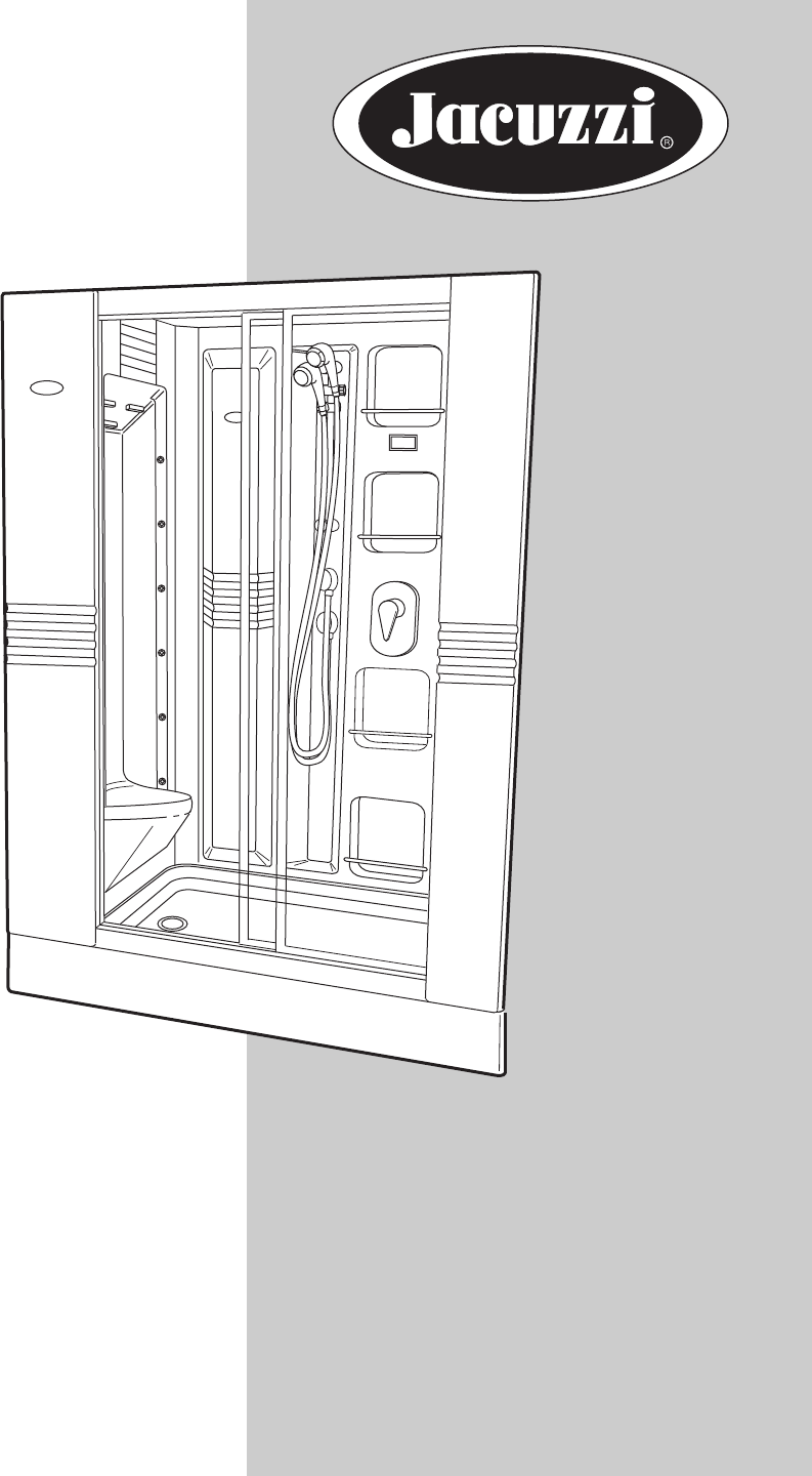
J-DREAM IIShower SystemOWNER’S MANUALAssembly, Installation& Operating InstructionsTM
8Locate Base to provide assembly access to all sidesRemove Base from carton labeled Base/Top. Place Clear Top in carton to prevent damage. (The Clear
9Drain Fitting (provided with unit)Leave enough flexibility in the waste line to allow the end of the stub-out to be blocked temporarily in a positio
10Attach Seat Walls to Base (J-Dream II with stereo shown)Bolts (8)Nuts (8)GJAlign four holes on seat wall frameover base and insert bolts andtighten
11Attach Panel #2 to Seat Wall FrameSlide in panel feeding between frame and edge of seat wall. Align to frame and fasten panel to frame. Important:
12Attach Panel #3 to Seat Wall FrameSlide in panel feeding between frame and edge of seat wall. Align to frame and fasten panel to frame. Important:
13Install Back WallCaulk the bottom and sides of back wall where indicated in the illustrations below. Install fasteners. Now align the backwall par
BAA.CaulkWasher (10)CNut (3)DScrew (3)BBReinstall bolts (4)and washers (4)removed from seatwall and bracketSeat wall attaches topanel #1 and #4 inthre
15Attach Brackets to Seat Wall Framesand L Bracket to left Angle BracketJ-Dream II Owner's ManualBBACA17"58-3/8"TOP OFFRAMEScrew (2)Not
CaulkBScrew (3)CWasher (3)Nut (3)DTop View (right side)NotchSide View (right side)BScrew (3)CWasher (3)Nut (3)DTop View (left side)Side View (left sid
17Attach Door Frame to Angle Brackets and Base FrameBefore proceeding, make sure the seat walls are closed and fastened. See detail B on page 15. Ali
IMPORTANT SAFETY INFORMATIONREAD ALL INSTALLATION INSTRUCTIONSSave These Instructions for Future Use.Owner's RecordJacuzzi Whirlpool Bath does no
18Attach Top Frame to Door Frame,Back Wall and Seat Wall FramesPress/tap top frame into door frame, aligning notch in door frame with corner of top of
19Feed the four hoses and controller cable from the back wall and connect them as shown. The steam hose connectionuses a hose clamp while the other h
20J-Dream II Owner's ManualUse cable ties to attach the CD/Radio wire bundle to the cascade hose. The hoses from valves 1 and 3 and the steamhos
21Connect the hoses routed from the back wall as below (grayed lines are pre-attached). Connect the controller line. Thered and black leads in the C
22Bonding (top left hand side of right hand equipment seat wall)J-Dream II Owner's ManualConnect a #8 guage (10mm2) minimum solid copper bond wir
1. Make sure electric power is OFF at main breaker.2. Static test water supply hoses for leaks.3. Plug power cord into GFCI protected wall outlet.4. M
24Attach Front Panels to UnitRemove this screwbefore operationGroundWireSpeaker andpower leadsBAntennaWireRear view of CD/radioScrew (2)Tinnerman® Nut
25Place cover on top of unit. Align notch in cover with the corresponding notch in the top metal frame.J-Dream II Owner's ManualTop Cover
26Turn On Electric Power at Main BreakerOperate Unit and Check for LeaksAttach Bottom Front Panel to UnitEnclosureBaseFramePanelVelcro®Velcro®Removabl
27FIGURE 1. CONTROL PANEL AND DISPLAYFIGURE 2. MIXER CONTROLPart II: Operating InstructionsCONTROL PANELSystem control is provided by the electronic d
Part I Assembly & InstallationSpecifications _______________________________________________________________________ 2General Information _______
Starting the HydromassageThe J-Dream allows you to enjoy the benefits of a real hydromassage. The hydromassage is created by thecombined action of 16
29Care and Maintenance of SteamProsMaintenance of the Steampros includes flushing and visually inspecting for water leaks.To flush the units:1. Turn
Printed in the U.S.A.Printed on Recycled PaperPRODUCT SPECIFICATIONS ARE SUBJECT TO CHANGE WITHOUT NOTICE.USE INSTALLATION INSTRUCTIONS SUPPLIED WITH
32
Jacuzzi Whirlpool Bath Limited WarrantyShower System ProductWARRANTY COVERAGEJacuzzi Whirlpool Bath (the “Company”) offers the following express limit
RESPONSIBILITIES OF OTHERSInspecting the unit prior to installation is the responsibility of the installer or building contractor who acts on behalf o
WHIRLPOOLBATHRJ-Dream II Owner's ManualFRONT VIEWPRODUCT SPECIFICATIONS ARE SUBJECT TO CHANGE WITHOUT NOTICE.SPECIFICATIONS2TOP VIEWDIMENSIONS60&
Read all instructions before beginning assembly and installation.General Assembly InformationThe J-Dream II shower unit is installed into a niche with
Electrical requirementsYour J-Dream II, as it comes from the factory, requires a GFCI protected 240 VAC 3- wire 20 AMP 50-60 Hz circuit (2 conductorw
J-Dream II Packaging6 cartons packed together on a wooden crate.Contents of cartons:• Wall Panels• Door Frame• Base/Cover (includes product accesso
J-Dream II Owner's ManualLetters (A) are used in the illustrations of the assembly procedure.6FLAT WASHER 1/4"PAN HEAD SCREW#10-24 x 3/4&quo
7Rough-inWASHINGMACHINEOUTLETBOXCONNECT #8 GAUGE(10mm2) MINIMUM SOLIDCOPPER BOND WIRE TOTHE HOUSE ELECTRICALPANEL OR APPROVEDLOCAL GROUND. ANAPPROVED
Verwandte Produkte und Handbücher für Sanitärkeramik Jacuzzi J-DREAM II
 (5 Seiten)
© 2020, manymanuals.de. Alle Rechte vorbehalten. | 0.046 s |
 Manymanuals.com
 Manymanuals.de
 Manymanuals.fr
 Manymanuals.it
 Manymanuals.pl
 Manymanuals.cz
 Manymanuals.es
 Manymanuals-pt.com
Kommentare zu diesen Handbüchern